 |
| |
‧ |
Using Ethernet Modules as Controllers |
|
| |
|
What is GCL? |
|
| |
|
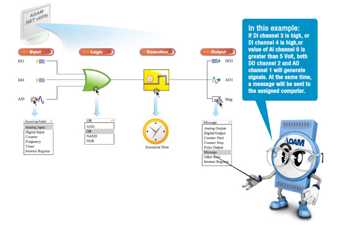
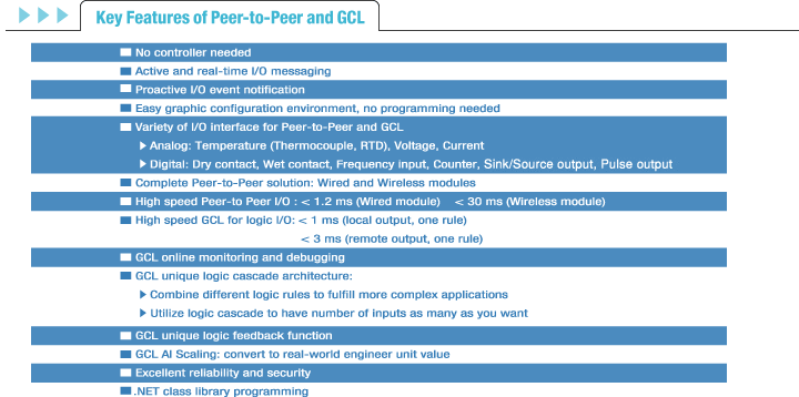
GCL (Graphic Condition Logic) gives Ethernet I/O modules control ability. Users can define the control logic rules through graphical configuration environment in ADAM.NET Utility, and download defined logic rules to specific ADAM-6000 Ethernet I/O module. Then, that Ethernet module will execute the logic rules automatically just like a standalone controller.
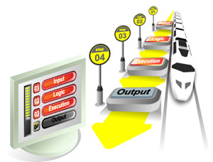
For each Ethernet I/O module, 16 logic rules can be defined. In the configuration environment of ADAM.NET Utility, 4 graphic icons show the 4 stages of one logic rule: Input, Logic, Execution and Output. (Refer to figure below). Users can simply click on each icon and one dialog window will pop-up for user to configure each stage. After completing all configurations, users can click one button to download the defined logic rules to the specific Ethernet I/O module. |
|
| |
|
 |
|
 |
| |
‧ |
Complete Graphical Configuration Environment |
|
| |
|
Unlike other text-based logic configuration utilities, Advantech GCL provides a complete graphical configuration utility, which is very intuitive to use. By simply clicking the icons, all related configurations can be done through the pop-up
dialog window. GCL is not only easy-to-use, but is also features very powerful functionality. |
|
| |
‧ |
Supports Both Local and Remote Output |
|
| |
|
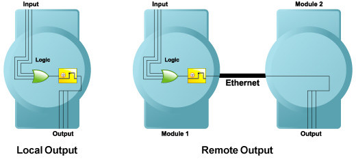
When users define the destination of Output stage (such as digital output, analog output, counter and pulse output),
users can choose either a local module or remote module as target. |
|
| |
|
 |
|
| |
‧ |
Cascade Logic |
|
| |
|
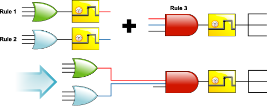
The output of one logic rule can be another rule. Therefore, different rules can be combined together. GCL provides
this kind of functionality called Cascade Logic. Once different rules are combined, it helps to create more input
numbers. For example, if users combine rule 1 and rule 2 with rule 3, the maximum inputs become 7 inputs.
(Two inputs of rule 3 will be rule 1 and rule 2, refer to figure below) So users can define complex logic architecture
to satisfy various application requirements. |
|
| |
|
 |
|
| |
‧ |
Distributed Cascade Logic |
|
| |
|
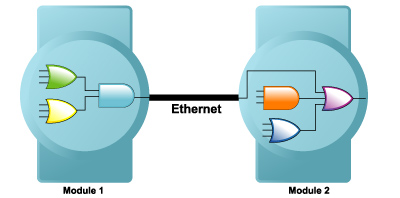
Users can assign other rule as output of one logic rule. In fact, that "Other Rule" can be on the same module, or on another remote module. So, one GCL logic architecture can operate across different modules. Several Ethernet I/O modules can be integrated into one complete logic system. |
|
| |
|
 |
|
| |
‧ |
Feedback Function |
|
| |
|
Users can assign input and output of logic rule to the same internal register, allowing GCL feedback. No hardware wiring is needed. In the example below, the 3rd input and the 3rd output are mapped to the same internal register, so the output value will transfer back to the input. |
|
| |
|
 |
|
| |
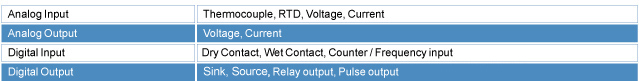
‧ |
Rich I/O Options |
|
| |
|
With Advantech complete ADAM-6000 Ethernet I/O modules, GCL delivers variety of input and output options. |
|
| |
|
 |
|
| |
‧ |
Fast Processing Time |
|
| |
|
Advantech GCL features extremely short logic rule processing time in market. When users choose local output
(the output channel and input channel are on the same module), the processing time (including hardware input
delay time, one logic rule execution time and hardware output delay time) is less than 1 millisecond. If users choose remote output (the output channel and input channel are on different modules), there will be extra communication time,
so the total time needed (including processing and communication time) is less than 3 milliseconds. |
|
| |
‧ |
Scaling (For Analog Input) |
|
| |
|
When configuring analog input condition, GCL provides linear scaling function to convert measured voltage/current value to its engineer unit value (such as temperature or pressure unit). Then users can use the engineer unit value to define the
logic condition. |
|
| |
| ‧ |
Online Monitoring |
 |
| |
After users complete all GCL configurations in ADAM.NET Utility, they can simply click the "Run Monitoring" button. Then users can see real-time execution workflow of logic rule on ADAM-6000 modules. Besides, current input values will also be displayed. This greatly helps users to maintain the system easily. |
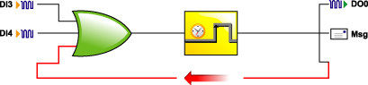
| ‧ |
Sending Messages |
| |
In GCL, you can define your customized message. When conditions are satisfied, message, module's IP and I/O status will be sent to defined PC or device. |
| ‧ |
Local DO Status as Input Condition |
| |
In GCL, you can read the local DO channel status and use it in the input condition. So you can define logic rule based on local DO status. |
|
|
| |
|
 |
